Borg Cube Server
It is not a secret that I am a Star Trek fan. It is also not a secret that I have a special passion for technology.
Recently, I have found a new hobby: 3D printing. And if that was a secret, well, it’s not anymore 🙂
And I’ve been thinking, what project could I undertake that would include a little bit of Star Trek and a little bit of technology?
Idea
The Star Trek universe is filled with fascinating technologies. Some of these technologies have become common in our world, or perhaps even more advanced than depicted in Star Trek (such as automatic sliding doors, smartphones, or Bluetooth headsets), but there are still technologies that we can only dream of (like teleportation).
Between them, there is another category of technologies from Star Trek that is currently being developed in the real world. We’re talking about things like spacecraft. Currently, they are at an early stage, but it feels like there is something on the horizon 😉
Since I started playing with 3D printers, I’ve been thinking about what objects from Star Trek I could print. And the most logical option seemed to be a spaceship as an ornament.
Almost 10 years ago, I decided that I needed a computer to serve as my personal server. A simple computer that would be connected only to the internet, without a monitor, keyboard, or mouse. Initially, I used a Banana Pi board (https://wiki.banana-pi.org/Banana_Pi_BPI-M1) and it had a simple git server. Then I added a hard disk, and it became a mini-NAS. And it kept growing until it became a full-fledged computer, with an Intel i3 processor, 8GB of RAM, and seven hard disks inside. Considering the seven hard disks, it wasn’t easy to find a case that wouldn’t take up half of the room, so I made several improvisations. But, being improvisations, they weren’t very reliable and didn’t look very good.
Since I started playing with 3D printers, I thought it would be a good idea to make a specially designed case for my server.
And that’s how I came to the conclusion that instead of doing two projects, it’s better to do just one 🙂
The Choice
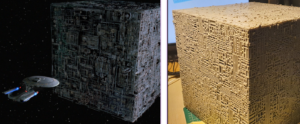
A server case in the shape of a Star Trek space ship. Although there are many types of ships in Star Trek, in the end, there was only one choice: the cube-shaped ship of an extraterrestrial race called the Borg. Most ships in Star Trek have intricate designs with a lot of attention to detail. But not the Borg ships. The Borg don’t make things complicated. Cube, cuboid, sphere. Unlike others, they know that there is no air friction in space, so their space ships don’t need aerodynamic shapes. 😀
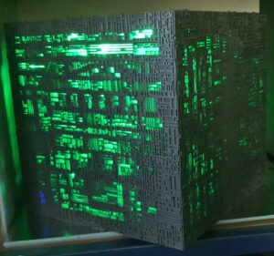
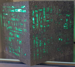
The design of the Borg ships is unique:
It looks as if they don’t even have an external hull; all the ship’s systems appear to be exposed. This was probably the way the filmmakers tried to show how different the Borg were and how little they cared about what we consider common sense.
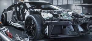
I wonder what a car made by the Borg would look like?
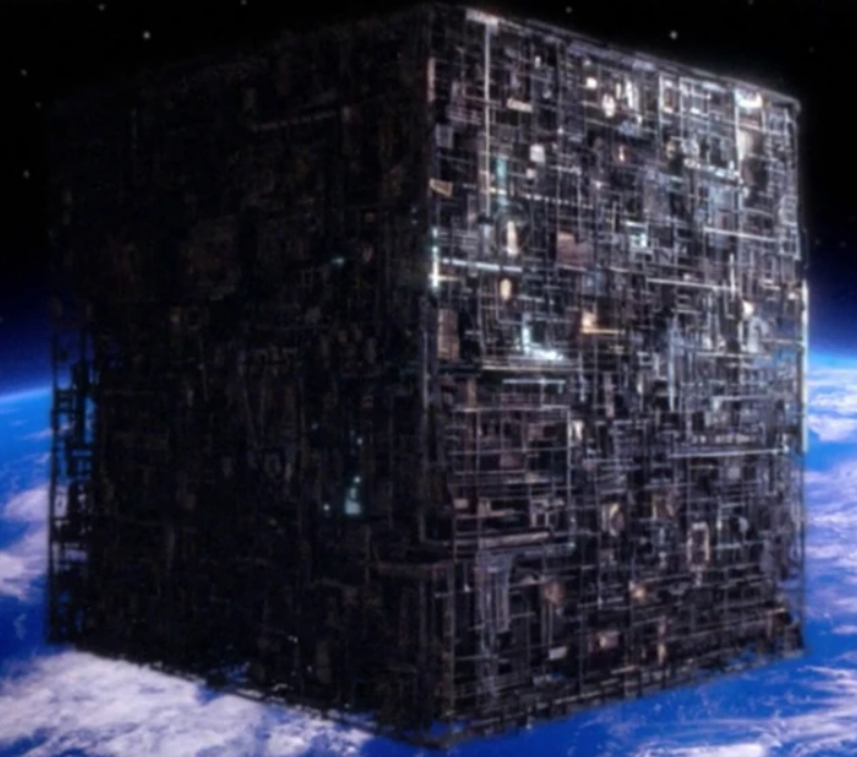
At first glance, it looks like a ship designed and built by amateurs who don’t even know how to protect their vital systems with a hull. It appears to be a prototype that could disintegrate at any moment, like a pile of scrap floating in space. All of this strongly contrasts with the capabilities of the ship. Tank manufacturers take pride in the thickness and performance of the armor that envelops their war machines. The Borg, on the other hand, send a ship without any kind of (visible, at least) external hull into battle. Nevertheless, it is capable of eliminating nearly 40 Federation space ships in an extremely short amount of time.
The cube ship becomes terrifying through its resilience and strength, a sensation amplified by its completely alien design, in stark contrast to everything we are accustomed to.
But being just a movie, the Borg ship has a certain “je ne sais quoi”… It seems to be designed for efficiency and reliability, completely disregarding aesthetics. Yet, that’s precisely what gives it a distinct aesthetic… a kind of technological steampunk. And my computer needed a reliable and suitable case for its peculiar configuration. The cube shape only helps with that 🙂 And the design makes it stand out.
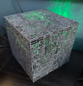
So, Borg Cube it is! 🙂
Thingiverse
Considering the complexity of creating a 3D model for the Borg Cube’s exterior, I started searching for existing models. The best one I found was on the Thingiverse platform: https://www.thingiverse.com/thing:3326170.
The model was quite detailed, but it had some disadvantages, such as being too small for my motherboard and my collection of hard disks. Another drawback for me was that the model was designed as a desktop computer case, so all the ports were exposed at the back:
If someone wants a Borg Cube-shaped case for a regular computer, the above-mentioned case is excellent.
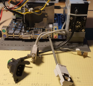
However, all I needed was the power button, a power cable, and a network cable. And to avoid any regrets later on, I decided to add two additional USB ports. Therefore, I decided to take the model from Thingiverse and modify it to better suit my needs for the server.
Numbers
The length of the cube edges in the initial model was approximately 250 mm. Although 250 seems like a round number, it didn’t seem suitable to me. I looked to see if I could make the edge length a perfect cube. However, 216 (63) was too small, and 343 (73) was too large. So I had to settle for a perfect square: 256 (162). As a bonus, 256 is also a power of 2 (28). Or, taking the calculations further, 256 = ((22)2)2. But let’s stop here with the mathematics 🙂
The motherboard I had fell between the microATX and flexATX sizes. The power supply was flexATX. The hard disks I had ranged from 2.5″ models with a height of 7 mm to 3.5″ models. The largest hard disk I had measured 102 mm × 25 mm × 146 mm.
Considering all these dimensions, the 256 mm edge length was suitable. The exterior size of the cube was 256 mm. Each face of the cube had a thickness of 7.5 mm, reducing the interior space by 14 mm. However, the remaining 242 mm was sufficient to accommodate everything I needed inside the case.
Design
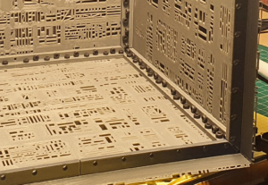
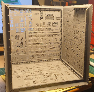
While examining the model from Thingiverse more thoroughly, I noticed that it was composed of a template. Although each face of the cube appeared unique, in reality, almost every face contained the same pattern repeated four times, but rotated/mirrored in various ways.
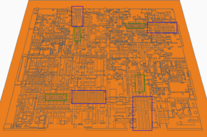
In the image above, two distinctive elements can be seen on the same face of the cube. Considering that it took me some time to realize this trick, I decided to apply it as well.
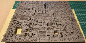
Because my model was slightly larger, I chose to place 9 models on the same face. Below is one of the faces designed by me. Upon closer inspection, the same distinctive elements can be seen as in the original model:
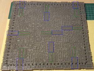
And without highlighting:
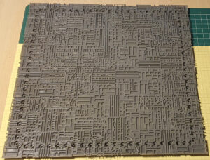
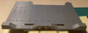
The above face is the bottom face of the cube and it is the only one without ventilation holes, but with the most screw holes. This is another difference from the original model, which had thin faces that were glued to each other using an angle bracket. I chose to make the faces thicker and attach them to the angle bracket using screws instead of glue. This choice means that the faces, being thicker, take more time to print and consume more material. However, I have had so many negative experiences with glue coming undone at the most inconvenient times, so I switched to screws despite the aforementioned disadvantages. The only faces of the cube that have visible screw holes are the bottom and the back faces. The top, left, right, and front faces are attached to each other internally, allowing the screws to be as concealed as possible.
Yes, I probably used 10 times more screws than necessary 😀
By the way, the screws used are M3, with lengths of 8mm and 12mm, depending on where they are placed. Generally, the screws on the interior are 8mm long, while the ones that screw in from the exterior are 12mm long.
The 3D model can be found on Thingiverse: https://www.thingiverse.com/thing:6095807
Assembly
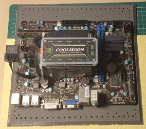
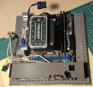
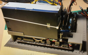
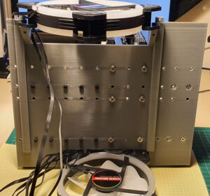
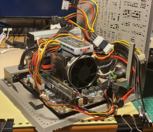
With the exception of connectors, which are attached to the back face, all components are mounted on the bottom face of the cube. The first one is the motherboard, secured using 6 nylon standoffs.
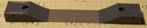
After the motherboard, the power supply follows, for which we have a bracket to hold it above the motherboard.
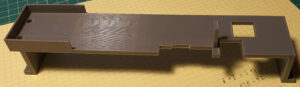
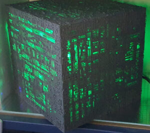
The power supply bracket also integrates two LEDs, one for power and the other for hard disk activity. The LEDs are visible through the case.
If it seems like it was filed in one place, that’s right! 😀 After trying to place it over the motherboard, I noticed that it obstructed a couple of connectors. I thought the two connectors would fit under the bracket, but I was mistaken 😀
But don’t get me wrong, that was not the only mistake; I printed this part in various shapes about 5 times. 😀
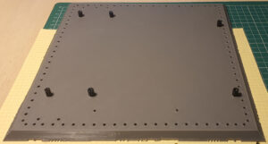
And speaking of trial and error, as you can see, the bottom face has some screw holes. To make sure I got the dimensions right, I scaled down the thickness of the model to 0.5mm and made several attempts until I found the correct placement for the screws.
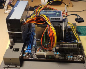
And with the aforementioned support installed, the power supply can be added.
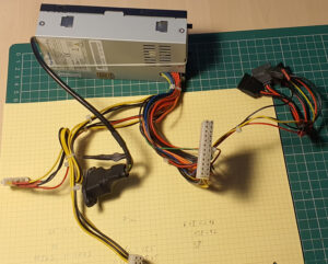
The power supply has been slightly modified. Since I have 8 hard drives (yes, one more than where I started), I have added more power connectors for them:
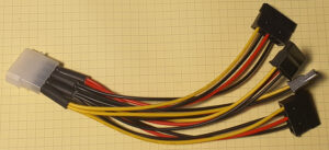
Plus a multiplier:
And finally the installed power supply:
Below the power supply support, the connector for the external USB ports is attached to the motherboard.
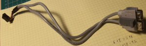
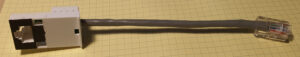
The other extension is for the network port:
You have probably already noticed from one of the previous pictures that no port on the motherboard even comes close to the back face. I did this intentionally because I don’t need that many ports, as I mentioned earlier. Below is an image comparing the available ports on the motherboard versus the ones needed for my project:
Why not expose all the ports on the motherboard? Well, it ruins the design! 😀
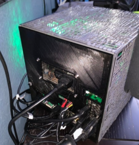
Take a look at how the backside looks with a minimalist set of ports:
The extensions are attached to the back face using small pieces specially designed for this purpose:
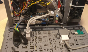
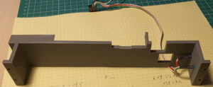
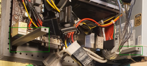
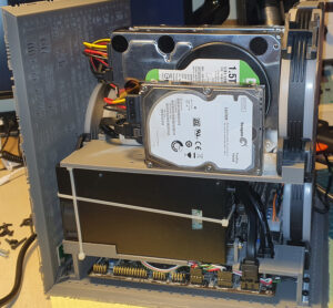
Before attaching the bottom and back faces to each other, two additional pieces need to be installed. The case is designed with two levels. The lower level houses the motherboard, power supply, and LED controller. The upper level is intended for the hard drives. The mentioned pieces are two supports for the harddisk tray that separates the two levels, marked in green below:
Now we can assemble the two faces:
And this is how it looks from the back:
Very discreet 🙂
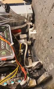
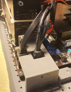
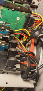
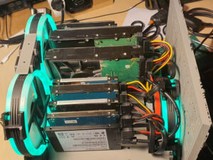
In the pictures above, you can see some odd SATA cables. That’s because I tried to remove the thick insulation and keep only the wires. I had eight hard drives in a very tight space, and one of the biggest issues was the rigidity and thickness of the cables. Although the cables worked fine, I decided to replace them with more flexible and shorter cables. This was mainly to ensure that no problems would occur later, such as a short circuit or damaged cable over time.
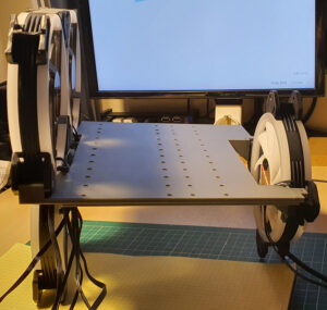
And speaking of hard drives, this is the harddisk tray that separates the levels and where the hard drives are mounted:
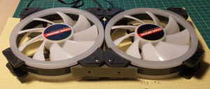
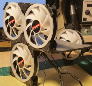
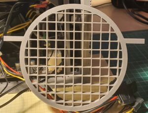
The harddisk tray is supported at the back by the two mentioned supports, and at the front by a fan. In total, there are four 120mm RGB fans:
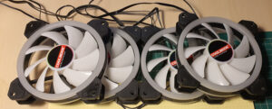
Two are placed at the top front:
The other two are positioned, one at the bottom front and the other at the back:
Yes, the fan brackets too had to be “adjusted” a bit 🙂
The hard drives are mounted on the created support:
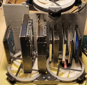
The screw holes were designed to accommodate both 2.5″ and 3.5″ hard drives of various thicknesses.
Because the rear fan is very close to the hard drive connectors, I designed a grill to keep the cables away from the fan blades:
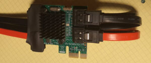
And speaking of the eight hard drives, the motherboard only provides four SATA ports, so I had to install a PCIe card with an additional four ports:
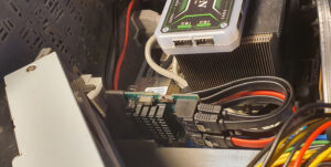
I couldn’t avoid it, I had to apply a bit of glue between the motherboard and the PCIe card to prevent it from accidentally coming out of the slot.
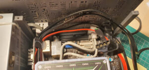
And here are the SATA cables connected directly to the motherboard:
Now all the cables should be connected, and the system should be ready for adding the hard drives and fans:
In the above picture, the bracket for the bottom front fan is also installed.
And with that, it’s time to connect the fans to the controller, install the fans-harddisks assembly into the system, and connect the hard drives.
The picture below shows how important the front fan grille is 🙂
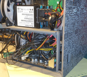
I know that the cable management in this PC is disastrous, but in my defense, the Borg didn’t seem too concerned either about cable management:

However, I would be happy if someone has any ideas for cable management for this project 🙂
Now that everything is connected, the best idea is to plug it in and see if it works! 😀
Great! It’s working! 🙂
After turning it off and unplugging it, we can attach the remaining four sides.
The remaining four sides are secured on the inside using the specially designed brackets:
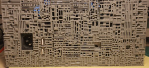
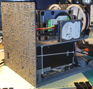
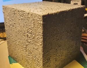
Another design idea. In the original model, the case had regular ventilation holes, which was more suitable for a PC. However, I chose to make this part look different. I copied a small piece from the original model and enlarged it to cover the entire surface of one side. For each side of the cube, I copied a different, but not necessarily distinct, part.
And that’s about it! We close the case, put it in its place, and power it on!
Technical Details
Some details about the server itself and the 3D printing process.
About the Server
Of course, it runs Linux. 🙂
The hard drives are either from old computers or purchased second-hand. For data safety, they are configured in RAID arrays (https://en.wikipedia.org/wiki/RAID). Nonetheless, important data is stored on Google Drive 🙂
The web page from which you are reading this article is also hosted by the Borg Cube server 🙂
Being a server, the computer is configured in the BIOS to automatically power on when plugged into a power source. This means that if the power goes out, the server will automatically start when the power returns (maybe I should also get a UPS).
At the time of writing this article, the server has been running continuously for over 56 days without a restart 🙂 The last restart was performed due to a Linux kernel update.
About 3D Printing
Because it is a very complex model, 3D printing takes quite a long time. At the settings I used (which are quite common among 3D printing enthusiasts), it took about two days to print one face. So, a total of 12 days of buzz-buzz from the 3D printer just for the six faces of the cube 🙂 The printer I used is the Anycubic Mega X.
Just when I started printing this project, I began having issues with the 3D printer; it would stop randomly after a while, and it took me a long time to figure out what the problem was. I don’t even want to know how much time I wasted on that issue. Due to that, I don’t remember exactly how long it took me to print all the parts. Plus, some parts had to be modified and printed multiple times.
For me, it’s not so frustrating when I make a mistake in a model and have to modify and reprint it. Sometimes I could have measured the dimensions more carefully, and other times there are things that, as a beginner, I don’t even know how to measure, so printing multiple versions until I get it right seems like a normal process to me. What annoys me much more is when the printer acts up! 😀
But when everything goes well (and I have to admit that this is the norm, with malfunctions being exceptions), the process of modeling an object on a screen and then slowly seeing it come to life (I could spend hours watching the 3D printer at work; it’s simply hypnotizing) and later being able to physically hold it in my hands gives me a great sense of satisfaction! It’s almost like having a replicator from Star Trek! Almost… 🙂